


Next: 4. The DSI Kernel
Up: An Architecture for Parallel
Previous: 2. A Primer
Subsections
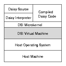
This chapter describes the design of DSI's virtual machine,
the lowest level component of the DSI hierarchy
(see figure 4).
Figure 4:
DSI Virtual Machine
|
DSI's virtual machine provides a low-level abstraction of the physical
machine architecture (memory interface, processor state, instruction set,
interrupt mechanism and processor interconnection topology) that forms
a portable foundation upon which the rest of DSI and Daisy is implemented.
The virtual machine approach provides several significant benefits:
-
It provides a modular way to port to new target architectures.
The rest of DSI is implemented on top of the virtual machine,
and Daisy on top of DSI, so the virtual machine isolates most of the
machine-specific implementation dependences.
For reasonably similar architectures, only the virtual machine layer
needs to be ported.
Substantially different architectures may require parts of the
microkernel to be rewritten for performance optimization, however.
-
It allows critical or missing functionality to be implemented
as virtual instructions which can be mapped as efficiently as possible to
the host architecture.
This helps identify key areas in which hardware support could be
helpful.
For example, cell allocation is such a frequent occurrence during
applicative language execution that it is supported by instructions
in the virtual machine.
This indicates that hardware support for allocation would be extremely
helpful for efficient execution of applicative languages.
We summarize these areas in section 3.6.
-
It documents the minimum hardware capabilities and functionality
required to implement the system, and delineates (potential)
hardware components from software.
This provides a sort of high-level blueprint for constructing a
machine for a native, self-hosted DSI environment or for implementing
DSI directly on a target machine, bypassing the host operating system.
3.1 Memory Interface
's virtual machine
specifies an architecture oriented toward list processing,
and its memory interface reflects this orientation.
The elemental addressable unit of memory is the cell,
a 64-bit word that conforms to one of several fixed formats.
Cells are classified at the storage management level by a
particular configuration of data and pointer fields.
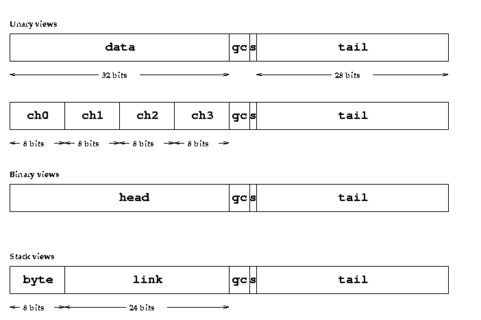
Figure 5:
Cell Storage Types
|
Figure 5 shows three storage classifications for
cells.
- Unary cells contain thirty-two bits of raw data and
a reference.
The data field can be accessed and interpreted in one of several formats,
including signed integer, single-precision floating point or packed bytes.
- Binary cells have fields head and tail,
each containing a reference.
- Stack cells contain a byte of data, a pointer and
a reference.
Cells have additional small bit fields used for various
purposes such as garbage collection and processor synchronization.
These fields are described where applicable.
The memory interface is facilitated by processor registers that conform
to one or more of these cell views
and machine instructions for accessing or allocating cells in
those views.
3.1.1 Tags and Types
All scalar data types and compound data structures are represented
by cells or linked graphs of cells.
Tagged pointers are used to accelerate suspension
detection and run-time type checking [Joh90,SH91] .
We will hereafter refer to a tagged pointer as a reference or
citation; a raw or untagged pointer is simply a pointer.
A reference contains three bits of tag information and twenty-four
bits of pointer information.
A reference's tag implies something about the storage class
of the cell to which it is pointing, and vice versa,
but tags and storage classes are different entities;
the distinction is clarified in chapter 5.
Briefly, a tag is a logical typing mechanism;
it says that the object to which the reference points is a list,
a number, etc.
These objects have underlying representations using one or more cells
conforming to a particular storage class;
e.g. a list reference points to a binary cell.
We may refer to a cell's type as either the cell's storage class
or its logical (reference tag) type.
In the former case the types are unary, binary and
stack;
in the latter case the types are list, number, and so
forth.
3.2 Processor State
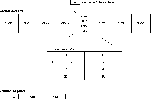
Figure 6 depicts the virtual machine state for a
single processor node.
Figure 6:
A Processor Node's Register State
|
The register file consists of a set of context windows.
Each context window holds a single process (suspension) context.
The context window pointer () always points to the currently
running process.
Control is transferred from one resident process to another
by directly or indirectly changing the .
This method of context switching allows several processes to be
multiplexed rapidly on the same node, and provides a mechanism for
interrupt handling.
The number of context windows (and consequently the maximum number of
simultaneously register-resident processes) is implementation
dependent3.1
Many current RISC-type architectures implement some form of register
windows (e.g. the Sparc architecture) or have a large register
set with renaming capability,
both of which are capable of implementing our context window model.
Context windows can also be implemented in memory, using
register-based pointer indirection for the .
Each context contains four fixed storage class cell registers:
, of type unary, , of type stack,
, of type binary and , type unary.
These registers are further subdivided into smaller addressable
fields reflecting the cell views as described above.
Registers , , , and are references,
is a byte, is a pointer and and are 32-bit
raw data words.
A context window's state is identical to that of a suspension's,
and the kernel swaps suspensions in and out of the context windows
as necessary using the ldctx and stctx instructions.
Suspending construction provides the basis for the design of
's process structure.
Suspension creation and coercion is the implicit behavior of
any code that builds, traverses, or otherwise manipulates data
structures.
Process granularity is much finer than in conventional languages;
accordingly, suspension manipulation is a critical performance issue.
This is reflected in 's suspension design.
Its small, fixed-size state (32 bytes) can be quickly allocated,
initialized, loaded and stored.
Conditional probes
(e.g. hdc, tlc) provide implicit detection and dispatch.
Because these and other suspension manipulation operations
(e.g. suspend, ldctx, stctx) are implemented as
instructions, they can be optimized at the lowest level of
implementation for best performance on the host architecture.
In addition to the context windows, there are several global
transient registers that are accessible from any context
on the node.
These are used as fixed operands by certain instructions and are
also used as general-purpose registers for passing data between
processes in different context windows.
Registers and are references.
and are untyped cell registers;
they can be accessed in any storage format via the appropriate field
name (e.g. WRK.ch1 or WRK.hd).
A process can only access the registers in its own context window
and the transient registers;
the kernel is the only process that has global access to all windows.
The memory subsystem has some private registers that are
described in chapter 5.
There are also some registers devoted to signal handling that are
described below in section 3.4.
3.3 Instruction Set
employs a load/store architecture that is similar in many
respects to general-purpose RISC microprocessors.
Its instruction set differs primarily in that it is very list (cell)
oriented with dedicated instructions for allocation.
Instructions operate on registers or immediate constants.
There are explicit instructions for reading from and
writing to memory in the cell format.
Instructions fall into the following general categories:
- Load
instructions read cells and cell fields from memory into registers.
We use the terms fetch and load interchangeably.
There are two kinds of loads:
conditional loads generate a trap if a suspension reference
would be returned to the destination operand,
unconditional loads do not.
Conditional loads are the basis of suspension transparency and efficient
detection, supported right down to the machine level3.2.
- Store
instructions write register contents to memory.
Like loads, there are conditional and unconditional versions of stores.
The conditional versions will fail on any attempt to overwrite a
non-suspension reference;
this feature can be used to arbitrate interprocessor suspension
scheduling (see [FW78d]),
although DSI has more generalized primitives (e.g. atomic add/and/or)
that can be used for more sophisticated coordination schemes.
- Allocation
instructions allocate cells from memory and initialize them using
register contents in a single operation.
This could be considered a special type of store operation.
Data creation (i.e. cell allocation) is such a frequent occurrence
in applicative systems that it warrants special consideration at the
machine instruction level.
This is discussed in more detail in section 3.5.1
and chapter 5.
- ALU
instructions provide simple arithmetic and logical operations on
registers.
These instructions are similar to those found on any traditional
microprocessor.
- Signal
handling instructions are used to control and manipulate the
hardware exception state.
3.4 Signals
exceptions and interrupts are handled under a common
signal mechanism.
Signals may be generated by hardware interrupts (e.g. timers,
devices), instruction traps (e.g. a conditional load) or
explicitly by the signal instruction.
Some common uses of signals are:
- Conditional loads whose result is a suspension reference.
- Allocation instructions which invoke garbage collection.
- I/O activity associated with a device.
- Timer interrupts for context switching.
- Bad references or ALU errors.
- Tracing and machine-level debugging.
- Interprocessor synchronization.
There are 32 possible signals, enumerated and prioritized
from lowest (0) to highest (31).
Depending on its use, a signal can be sent to a single processor or
multicast to all processors.
An example of the former case is a localized conditional-load trap
occurring on a processor/memory board;
an example of the latter is a barrier synchronization signal
such as used in garbage collection.
The signals are assigned by the kernel and are listed in Table
1 in chapter 4.
DSI uses a process-oriented approach to signal handling,
in contrast to the stack-oriented approach used in most
imperative systems.
The latter usually handle exceptions
by pushing state on the currently executing process stack
(or a system stack) and invoking an exception-handling procedure.
Under DSI,
when a signal is delivered to a processor node it causes a context
switch via a change of the context-window pointer (CWP) to an
alternative resident handler process.
The handler might be the kernel or another process (subsystem)
designated to handle that signal.
The currently executing process is
suspended by the context switch, but its state is not side-effected.
Neither is the state of the handler process;
that is, no continuation is forced upon the handler,
it simply resumes at the point where it had left off previously.
Thus, the only action of a signal is to context switch to a handler
process,
which must be designed as an iterative signal handling loop.
DSI instructions are designed to be restarted in the event of a
signal preemption3.3,
so the preempted process can be restarted (if necessary) by
changing the CWP back to the appropriate context window.
However, since process state is not side-effected by signals
(and assuming none in the surface language),
it is not necessary to maintain a stack or other structure to recover
from the effects of some permutation of delivered signals.
All that is required is a scheduling algorithm that results in the
the proper processes being rescheduled,
and this is provided by DSI's demand-driven scheduling3.4.
This approach to exception handling fits well with the
applicative framework that underpins the rest of DSI.
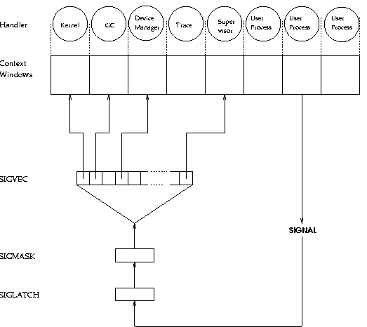
Figure 7 shows DSI's signal handling architecture,
which works like a state machine.
Figure 7:
Signal Handling
|
The signal lookup table maps incoming signals (on- or off-node)
with the current value of the CWP to determine the new value of
the CWP.
This allows the same signal to be mapped to different handlers depending
on which context window is active.
Arbitration between multiple pending signals is handled by the fixed
priorities of the individual signals;
the highest numbered unblocked signal has priority.
The kernel takes this into account when assigning signals
to services.
Delivery of signals is controlled by a pair of 32-bit registers:
SIGLATCH and SIGMASK.
Each bit in SIGLATCH corresponds to one of the 32 signals;
when a signal is delivered to the node it sets the corresponding bit.
SIGMASK is used to block action on signals registered in
SIGLATCH.
If a bit is clear in SIGMASK it inhibits the processing of the
corresponding signal in SIGLATCH;
i.e. the signal is effectively blocked.
This capability can be used to mask interrupts for critical sections,
to implement polled device drivers, etc.
The signal, tstsig, setsigmask and clrsigmask
instructions are used for manipulating the bits in these registers.
The preceeding discussion is concerned with signal handling at the
system level, on a per-node basis.
Signals are a system phenomenon and transitions are specified in
terms of context windows, not individual suspensions.
It is the kernel's job to micro-manage the context windows to map the
signals between the individual processes.
In order to handle the signal mappings of thousands of suspensions the
kernel has to handle some signals itself and swap suspensions between
the finite set of context windows and the heap as necessary.
Currently, this is done only for a few signals with fixed, implicit
mappings, such as the the conditional load and timer signals.
However, it should be possible to generalize this mechanism,
and by overloading one or more unused system signals, to carry a
variable number of user-defined ``signals'' on a
per-suspension basis.
This capability would provide the foundation for user-extensible
signaling and exception handling.
Assuming that a usable construct could be formulated for Daisy,
such a mechanism could be used for error recovery, event-driven
scheduling, port-based message passing and other systems-level
applications.
It is unclear at present whether and how demand-driven system
scheduling would conflict with event-driven user scheduling.
The incorporation of this kind of primitive would add another
source of non-determinism (besides multisets) into the system,
but given the underlying implementation of signals it is likely to
be ``safe'' non-determinism.
This is an interesting area that deserves further consideration.
3.5 Interconnection Topology
DSI assumes a shared memory, MIMD architecture.
Aside from that, the virtual machine does not specify a particular
processor interconnection topology,
primarily because that aspect of the architecture does not figure as
prominently in the programming of the machine given those
assumptions.
However, the host platform must provide a certain core functionality
to successfully implement DSI. This includes:
- 1.
- A globally-shared and addressable heap memory.
DSI's reduction and communication models rely heavily on shared
data structures.
Those models are unlikely to be viably implemented on anything other
than a physical shared memory machine (i.e. non-message passing).
The shared memory can be organized as a NUMA
architecture (see section 2.2.1), however.
NUMA architectures require special considerations for locality
that are not isolated within the virtual machine.
These locality issues affect the process (chapter 6) and
memory management (chapter 5) subsystems,
and are discussed in those chapters.
- 2.
-
Symmetric MIMD multiprocessing.
DSI assumes that all processors have the same basic configuration
and functionality, and are not organized hierarchically.
The distributed algorithms used assume a logical enumeration of
processor nodes, and a given node must be able to determine its index.
- 3.
- Efficient implementation of atomic 32-bit add, or,
load and store operations.
Atomic loads and stores are necessary to insure the integrity of
references in the heap.
The logical, bitwise atomic operations are used for interprocessor
synchronization and updates on shared data structures.
- 4.
- The ability to interrupt any processor in a ``timely'' fashion.
DSI's signals can be piggybacked on a single user-programmable
host exception, provided the overhead of native exception handling is
not significantly greater than DSI's own signal handling model
implies.
A polling approach can also be used, if necessary.
Any parallel architecture that shares these characteristics is
a suitable candidate for hosting DSI.
This type of architecture (MIMD shared-memory symmetric
multiprocessor) is common in emerging multiprocessors.
3.5.1 LiMP
Although the virtual machine does not specify a particular network
design, special architectures have been proposed.
In a series of papers,
Johnson ([Joh81,Joh85,Joh89c])
refines a buffered routing network as the basis for a
DSI multiprocessor.
Wise describes a layout scheme for implementing such a network
in [Wis81].
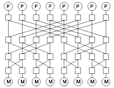
The network described is a Banyan design (see figure
8) connecting a set of
List Processing Elements (LPEs) to a corresponding set of
List Storage Elements (LSE's).
Figure 8:
A banyan network
|
LPE's have roughly the same architecture described for DSI processors
in section 3.2 above, but lack multiple context
windows and signals.
LSE's are intelligent memory banks, participating actively with the
network in supporting the LPE's.
Johnson [Joh81] classifies memory access instructions into
fetch (RSVP),
store (Sting) and allocation (NEW) requests, each having
a distinct network transaction profile between LPE's and LSE's.
RSVPs require a round-trip message from LPE to LSE and back to furnish
the result.
Stings are one-way requests requiring no acknowledgment.
NEWs are handled in unit time by a cell routing arrangement called a
NEW-sink, in which LSE's combine with the network switches to
route the addresses of free list cells back towards the LPE's.
Switches are endowed with buffers for the addresses;
whenever a switch transfers an address out of its holding area to its
outputs it requests a new one from its inputs.
The switches are biased to transfer addresses directly across the
network, but will transfer from the alternate input if demand is high.
The idea is to preserve locality under normal allocation rates,
minimizing contention at the switches for loads and stores,
but to disperse high allocation rates across the machine so as to
minimize hot spots.
Johnson presents simulation results of LiMP in [Joh81].
The fundamental motivation behind the NEW-sink is to move resource
management problems from software into hardware.
If the goal of the NEW-sink is to handle data distribution then the
goal of the Process-sink [Joh89c] is to manage
load balancing.
The Process-sink is a complementary operation in which LPE's
route free suspension blocks through the network to LSE's.
If LPE's only multi-task suspensions in their ``local'' space,
then idle LPE's will be able to provide more free suspension
blocks to the system than busy LPE's, effectively migrating
new processes to idle nodes and balancing the load over the system.
The behaviors of the NEW-sink and Process-sink are modeled in DSI
by a load-based allocation strategy described in chapter
5.
DSI's has been implemented on a BBN Butterfly multiprocessor,
selected because its shared-memory (NUMA) network architecture is
similar to the LiMP architecture described above.
The Butterfly differs from LiMP in that it uses a
circuit-switched (non-buffered) enhanced banyan network.
Each processing node contains a processor, a memory bank and network
interface called the PNC (Processor Node Controller).
Processors are tightly-coupled to their local memory bank,
but all banks are accessible through the switch, as though the graph
in figure 8 was folded laterally into a cylinder.
Each processor actually has two paths for memory access:
to its local memory over a local bus, or through the switch to
any other node's memory bank.
Each PNC arbitrates access to its memory bank between the processor and
the network.
Experiments indicate that in the absence of contention switch
access to memory is about four times as slow as local access;
with contention the switch access memory latency degrades even further.
This leads to special considerations for memory management, which we
generalize to all NUMA architectures.
3.6 Summary
Although 's instruction set is oriented towards list processing
it otherwise provides much of the same functionality as a stock
microprocessor, most of which are adequate for emulating a
virtual machine.
It is encouraging that stock hardware performance is improving
so rapidly and carrying with it the performance of symbolic languages.
Nevertheless, we could do much better, because there are a number of
areas in which relatively minor hardware enhancements would reap great
rewards in the execution efficiency of these languages, and narrow
the performance gap with traditional languages.
The key areas in which DSI would benefit from hardware support are
context windows, allocation instructions and DSI-style signals,
especially signals for trapping on reference tags, which would
benefit dynamic type checking and suspension detection.
Wise has identified a number of other features that would be useful for
hardware-assisted heap management, such as support for reference counts
[Wis85a,DW94].


Next: 4. The DSI Kernel
Up: An Architecture for Parallel
Previous: 2. A Primer
Eric Jeschke
1999-07-08
